An Introduction to Loop-Shaping Design for PID Control
Loop shaping is one of the primary methodologies used for designing classical controllers such as PID’s. In loop-shaping the controller structure and gains are selected such that the magnitude of the frequency response of the open loop transfer function has particular characteristics -- or a particular shape.
This article is the first in a series of articles discussing the control design process. It discusses how the open-loop shape directly influences the performance of the closed loop. Specifically it shows how to select the P, I and D terms of a PID controller to achieve desirable open and closed loop responses. The frequency response of the transfer functions is viewed using a Bode diagram.
This article discusses the design of continuous time controllers. Companion articles discuss the process of converting continuous time controllers into discrete time controllers suitable for implementing on digital hardware; and issues that must be considered when using fixed-point processors.
In this article each of the following topics are discussed:
- 1. The Loop and Controller Structure
- 2. The Proportional Term
- 3. The Integral Term
- 4. The Derivative Term
- 5. Low pass filter
- 6. Transforming the PID Structure
- 7. Conclusion
1. The Loop and Controller Structure
Figure 1 shows the standard closed-loop feedback configuration considered in this article. The open-loop transfer function is calculated as the series connection of all components in the loop. In this case the open-loop is equal to K×P. The closed loop is the overall input-output response when the feedback loop is closed. In this case it is the transfer function from the reference ref signal to the output y.

The controller in this article is assumed to be of the standard PID form:
![]()
For different plant models, the following sections discuss how to select the controller gains pidKp, pidKi and pidKd to provide a loop-shape giving acceptable closed-loop performance. Note that the derivative term includes a filter with a pole at plead to enable it to be realized. Selecting a suitable value for plead is also discussed.
2. The Proportional Term
The proportional term moves the magnitude of the frequency response of the open loop up or down and hence is used to set the cross-over frequency of the open loop. The cross-over frequency is the frequency at which the magnitude has a gain of 1 (or 0dB). This frequency is important as it is closely related to bandwidth of the closed loop response.
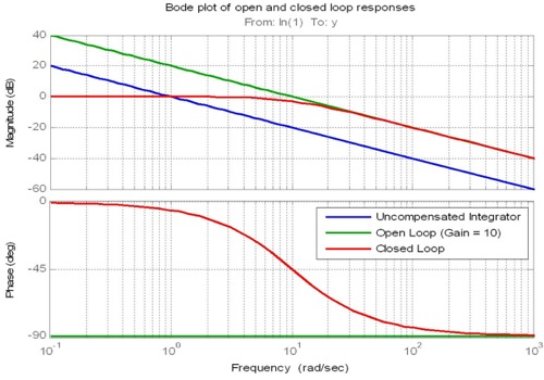
Consider for a moment the standard feedback configuration shown in Figure 1 where the plant to be controlled is a single integrator P = 1/s. The open-loop magnitude response of an integrator has a constant slope (or roll-off) of -20dB/decade at a cross-over frequency of 1 rad/sec. This is shown in Figure 2.
An integrator can be gain stabilized. That is, any constant gain feedback will act as a stabilizing controller when the loop is closed. This constant gain is simply a proportional controller. The gain raises or lowers the open-loop magnitude response hence setting the cross-over frequency. For the system shown in Figure 2 a constant gain of 10 has been used thus setting the cross-over frequency to be 10 rad/sec. When the loop is closed the cross-over frequency is the bandwidth of the closed-loop. This is also shown in Figure 2.
In an ideal system the proportional gain could be made (almost) infinitely large leading to an infinitely fast, yet still stable, closed loop. In practice that is not the case. Rather, two design rules of thumb come into play.
Firstly the sample rate of the digital hardware on which the controller is going to be executed needs to be considered. A typical rule of thumb is that the cross-over frequency should be set to be at least 10 times lower than the sample rate of the controller. Conceptually this ensures that the controller is running at a fast enough rate that it can adequately handle changes in the signal being controlled.
The second rule of thumb is related to the slope of the frequency response at the cross-over frequency. If the roll-off of the open-loop magnitude response at cross-over can be made to be close to -20dB/decade then the closed-loop bandwidth can be expected to be close to the cross-over frequency. Note that the integral and derivative terms, not just the proportional term, are used to control the slope at cross-over.
3. The Integral Term
The integral term is used to ensure a zero steady-state error. Consider again the standard feedback configuration of Figure 1, however this time with the plant:
![]()
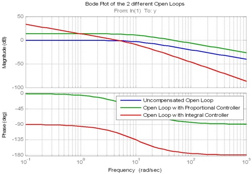
Now consider two controllers: one that is a proportional controller with gain K1 = 5; and another that is a purely integral controller K2 = 5/s. The Bode response of the uncompensated plant P and the open-loops with the two different controllers, K1P and K2P, are given in Figure 3. Note that the integral controller forces the open loop magnitude to be nearly infinite at very small frequencies, i.e. at steady state. It is this effect that forces the closed-loop to have a zero steady state error.
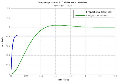
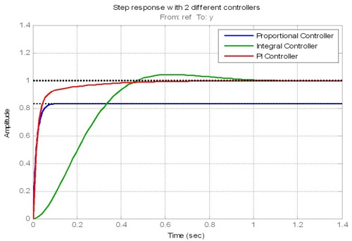
Step responses for the two closed-loops are given in Figure 4. The input reference is a step from 0 to 1. Hence for zero steady state error the response should also go from 0 to 1. This is not the case with K1. It is the case with the controller K2.
Note that even though K1 and K2 have the same gain value (of 5) they lead to very different cross-over frequencies (50 rad/s and 5 rad/s respectively). Ideally the incorporation of the integrator into the controller should not affect the cross-over frequency. That is, the integrator should only affect the loop response at low frequencies. It should raise the response at low frequencies but not affect the loop at higher frequencies, including the cross-over frequency. This is how a PI controller works.
Continuing with this example, assume that both a cross-over frequency of 50 rad/s and a zero steady-state error are required. This is achieved by adding a zero to K2 at some frequency below 50 rad/s thus removing the effects of the integrator at frequencies above the chosen frequency. A typical rule of thumb is for the effects to be removed at a frequency 4-5 times lower than the cross-over frequency. Unfortunately this would put the zero directly over the pole of the plant (at 10 rad/s) leading to pole-zero cancellation. For this simple example the zero could be placed either above or below the plant pole. A value of 5 rad/s has been chosen.
Hence a suitable PI controller is:

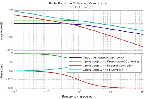
As shown in Figure 5 this controller shapes the loop the same as the integrator at low frequency and the same as the constant gain at higher frequencies, including at cross-over. These characteristics mean that the closed loop has zero steady state error and the same bandwidth as the proportional controller. The step response of the closed-loop with all three controllers is shown in Figure 6.
4. The Derivative Term
The derivative term is used to increase the initial speed of response of the closed-loop. This is achieved by allowing the rate of change of the error signal to pass quickly into the control signal. That is, if the reference signal changes quickly (e.g. a step change) then the control signal responds quickly.
However, a pure derivative term would also allow noise to propagate through the controller and affect closed-loop performance. Hence a pure derivative term is never used in practice. Rather it is used in combination with a low-pass filter where the bandwidth of the filter is set to trade off speed of response against noise propagation.
The transfer function of the derivative term within a PID controller can be written as the transfer function of a phase-lead filter. In a loop shaping design, it is this phase-lead filter that is designed and then transformed into a derivative plus low-pass filter combination. (See Section 6 for a discussion of this transformation.)
To see the effects of a phase-lead filter on the previous designs, consider the following controller:

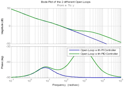
The open-loop frequency response is shown in Figure 7. Note that the phase-lead term increases the magnitude response at high frequencies, starting (as a rule of thumb) at about 5-10 times higher than the cross-over frequency. The pole and zero of the phase-lead transfer function are usually placed about a factor of 10 apart.
Importantly the phase-lead filter also adds phase to the loop, particularly at cross-over. This can help increase the overall phase margin of the closed-loop.
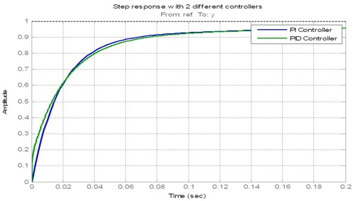
The closed-loop step response is shown in Figure 8. Note the faster initial response with the PID controller.
5. Low pass filter
In practice a low pass filter is often inserted before the PID controller. This helps to reduce the effects of noise propagating through the loop.
A design rule of thumb is to have the cut-off frequency of such a filter set at 5-6 times the crossover frequency. Any lower than this and the filter begins to affect the response at the crossover frequency, and hence the closed-loop bandwidth too much.
6. Transforming the PID Structure
The loop shaping methodology discussed in this article leads to a controller of the form:
![]()
However, traditionally a PID controller is written and implemented in the form:
![]()
Fortunately the two forms are equivalent. To see this, firstly note that by grouping of terms of different powers of s and rearranging them, the following equality holds:

The above equality can conveniently and compactly be written in the following matrix form:

The 3-row 3-column matrix on the left hand side of the above equation is invertible. Hence after using the loop shaping methodology discussed here to determine Klead, Kp, Ki, and plead the above equation can be used to calculate pidKp, pidKi and pidKd. These values may then be used in the implemented controller.
7. Conclusion
This article has described the basics of the loop-shaping methodology for designing continuous-time PID controllers.
The methodology requires the controller gains, poles and zeros to be selected so that the shape of the open-loop frequency response follows certain characteristics that are known to provide good closed-loop performance. Several design rules of thumb have been introduced and used to give the required shape while meeting design constraints such as those imposed by the speed of the processor on which the control loop will ultimately be executed.
Companion articles discuss the process of converting continuous time controllers such as those designed in the article into discrete time controllers suitable for implementing on digital hardware; and issues that should be considered when using fixed-point processors.
